
Scroll down for the written version.
In this tutorial, we’ll see how to create an assembly that has a component span.
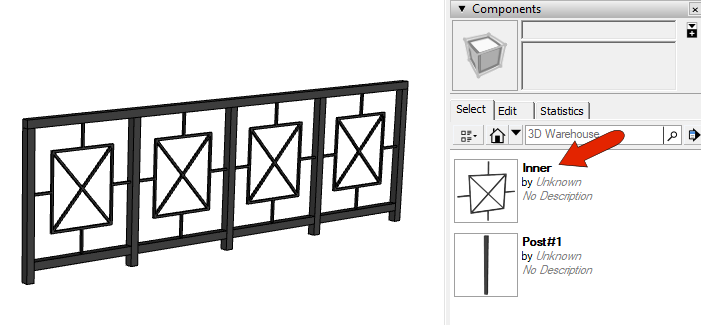
In a previous tutorial, we saw some examples of spans comprised of components. One example is Railing Assembly 4, whose span named “Inner” is a component.
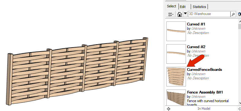
Another example is Fence Assembly 8, which has a component span called “Curved Fence Boards.” This component looks like this.
Now we’ll work through an example of how to create a similar assembly from scratch, which will contain a component span.
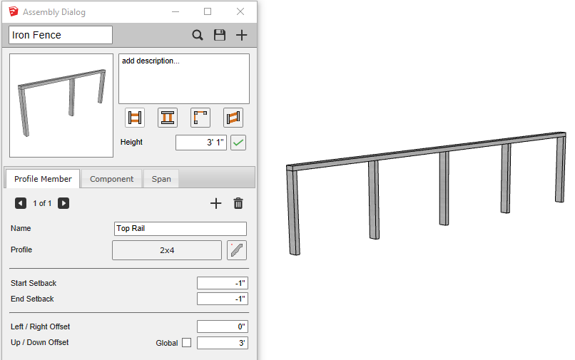
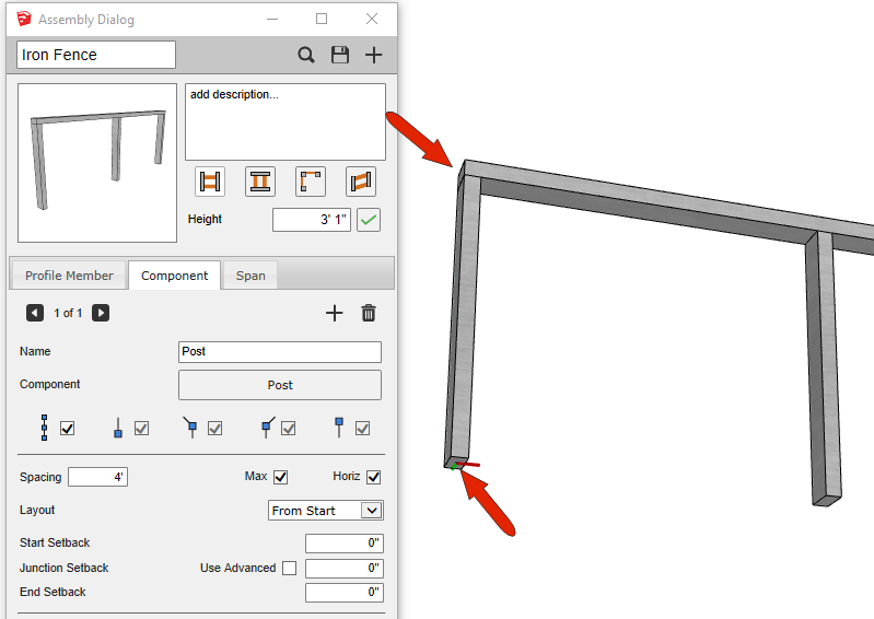
Here is a partially built fence assembly called Iron Fence. This fence has one profile member - the top rail. Note the -1” setbacks.
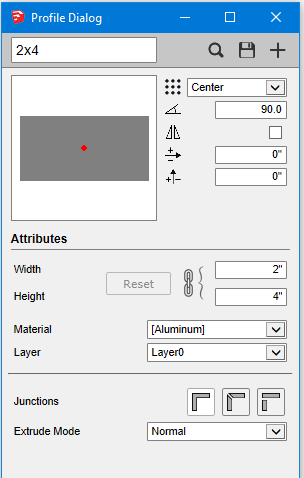
The top rail is based on a profile called 2x4, which is oriented like this and has a center placement point.
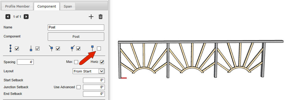
The one component in this assembly is called Post and is based on the same profile. These are spaced at 4’ max, and this component has its origin at the bottom center. This is why the top rail profile member needs the -1” setbacks.
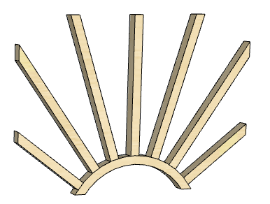
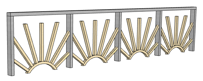
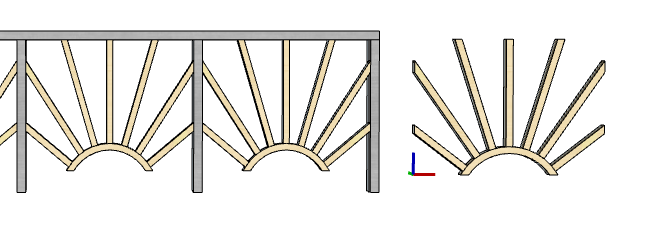
Here are the objects that will be used as spans between posts.
Make all objects into a component and set its axes. By default, the origin is at the lower left corner of the component’s bounding box, but we want the origin to line up with the center of the component. So use inference points at these two midpoints and place the origin.
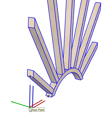
Name the component Sunburst.
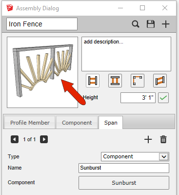
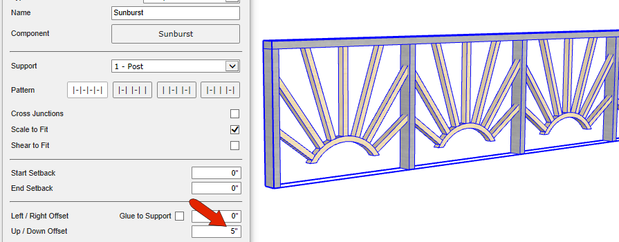
In the Span tab, add a new span, set its type to component, name it sunburst, and pick it from the model. You can see from the preview that some adjustments are needed.
Update the fence to see how it looks so far.
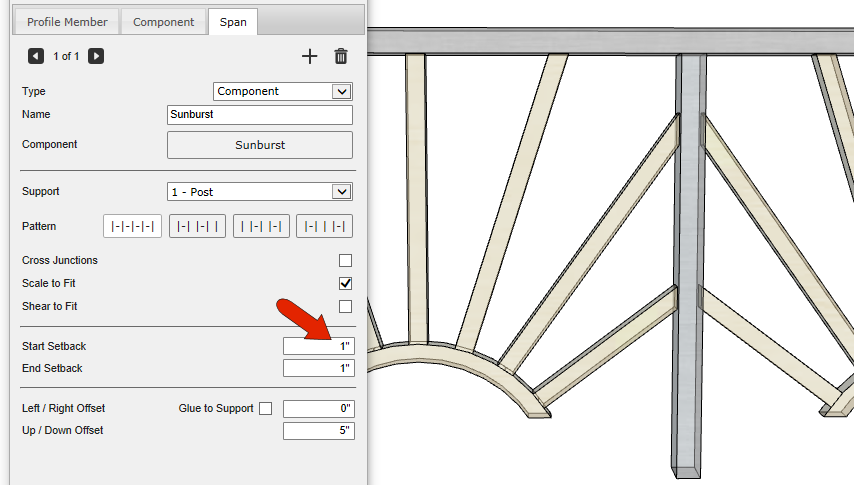
First, add a vertical offset of 5” to get the components off the ground, and properly aligned with the top rail. Later we’ll add another span below each component.
In looking at where the span components meet their posts, we can see that the objects continue inside each post.
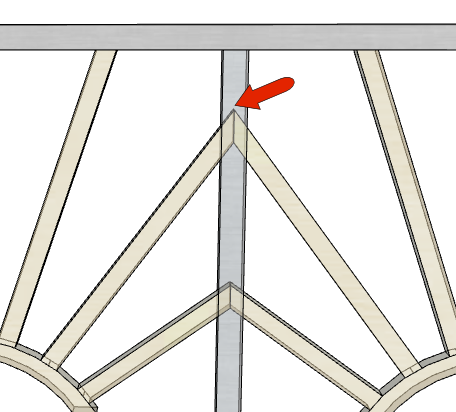
Component spans don’t have an Auto Trim option, and by default,a component's origin will be at the same location as the origin of the first support. Also, by default, the red axis of the span component will also point towards the second support by default. This can be seen clearly in X-Ray view - the component origin is directly above the post origin, which is at the post center.
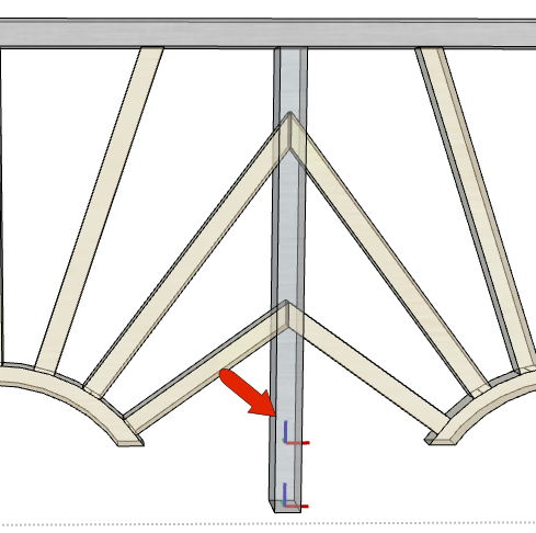
Also, Scale to Fit is enabled by default, which causes the component to be stretched along the red axis until it reaches the axes of the second support.
Because the posts are 2” wide in this direction, we need to add 1” setbacks at both start and end. Now the components meet the sides of the posts.
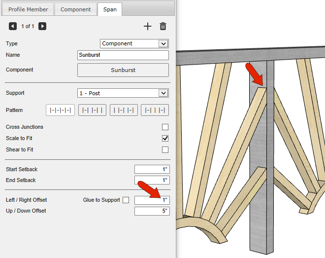
Because the span component origin is at its center, the spans are centered correctly within the posts. If each span is to be flush with the front of the fence, you could add a Left / Right offset. The value in this example would be positive 1”.
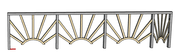
Also note that each span is a bit smaller than the original component. You can see this clearly when placing another instance of the original component. This is because Scale to Fit is checked, which means the component will stretch or shrink along the component’s red path direction, to accommodate the distance between posts.
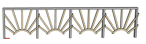
The post spacing in this example is 4’ max. Unckeck Max, and the components between most posts stretch a bit wider. But the one between the last two posts is squashed pretty tightly.
You could fix this by removing the last post.
Replace the post and bring back Max.
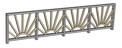
For the span, uncheck Scale to Fit, and now the components are all at their original size.
To complete the fence, bring back Scale to Fit, then add another span. This new span will be a profile member named Bottom Rail, which can be picked from the model by opening the fence group.
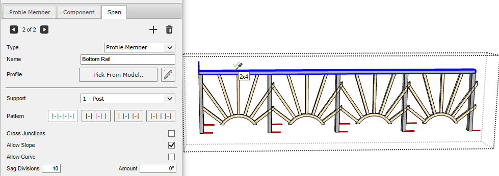
Use Auto Trim, change the vertical offset to 4”, and remove the 1” right offset from the previous component.
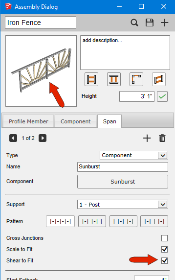
Going back to the component span, the Shear to Fit option is relevant for assemblies along a slope. The sloped preview shows how the fence would look.
Draw the fence along an angle.
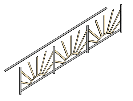
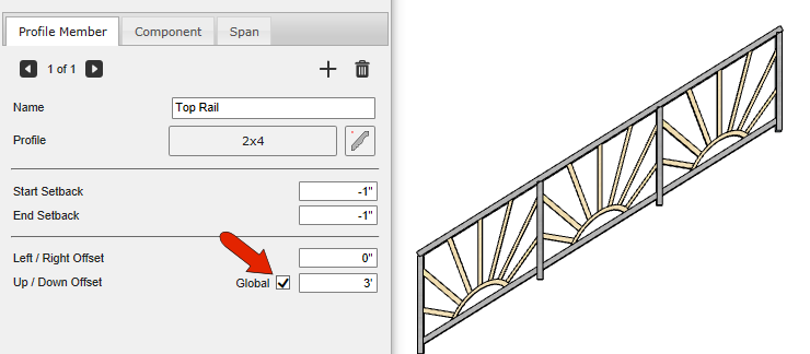
The top rail profile member can be easily fixed by checking Global for Up / Down offset.
The bottom rail span is already following the slope, but this isn’t an option for span components. But checking Shear to Fit will do the same thing. This option keeps the component’s red axis along the assembly path.
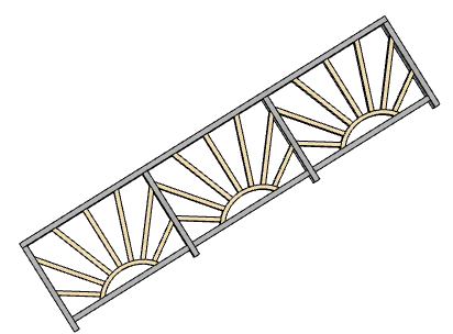
Now let’s see what happens when posts aren’t constrained to be vertical. First, remove Global from the top rail. For the component span, Scale to Fit is still needed, and removing Shear to Fit orients the spans correctly. The component’s red axis follows the slope, as does the red axis of the posts.
Comments
0 comments
Please sign in to leave a comment.