Profile Member - Start Setback
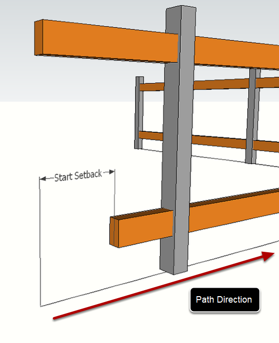
Start Setback defines the distance from the start of the assembly path that the Profile Member starts. You can use a negative setback distance to make the Profile Member start before the path of assembly.
Profile Member - End Setback
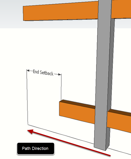
End Setback defines the distance from the end of the path that the Profile Member ends. You can use a negative end setback distance to extend the Profile Member beyond the path of the assembly.
Profile Member - Hide Start / Hide End
New in v4 - This setting allows you to hide the end geometry (faces and edges) of Profile Member parts. This technique is useful to provide visual continuity between Profile Members and components within an assembly. Remember to also hide the neighboring edges of the component when using this technique.
Profile Member - Up / Down Offset
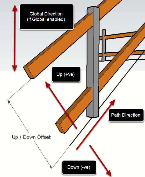
Up / Down Offset defines the vertical offset of the Profile Member path relative to the Assembly path. Enter a positive value to offset up and negative value to offset down.
Use the Global checkbox to force the offset direction to be along the model blue axis. Otherwise, the offset will be along the local up / down axis which may vary if the assembly path is not horizontal.
Profile Member - Left / Right Offset
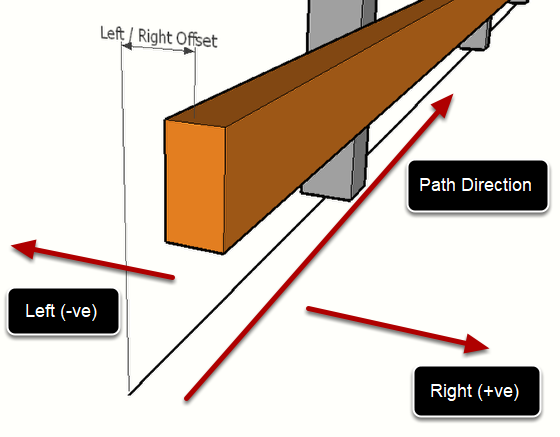
Left / Right Offset defines the horizontal offset of the Profile Member path relative to the Assembly path. Enter a positive value to offset to the right and negative value to offset to the left.
Component - Infill Checkbox
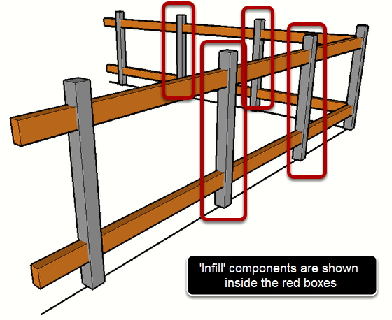
If the Infill box is checked, the component will be placed at regular intervals, defined by the following settings:
- Spacing
- Max (vs Fixed) Spacing
- Horizontal Distance (vs Distance along path)
- Layout
Component - Spacing
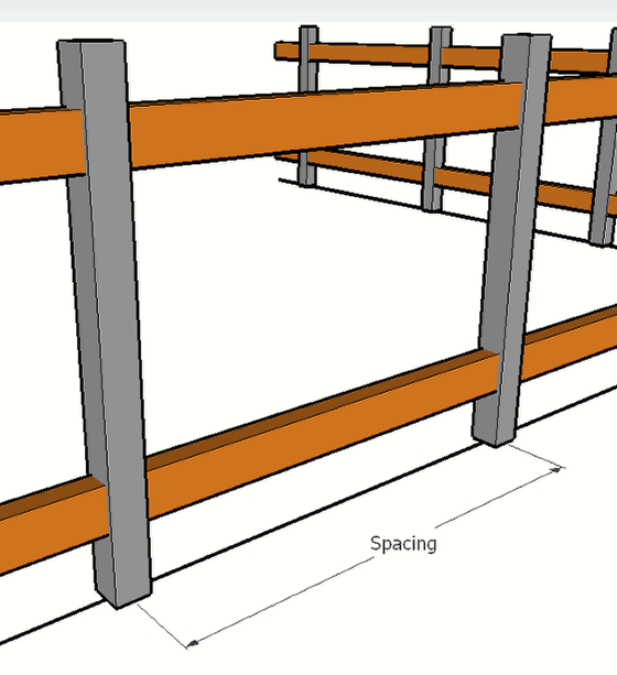
Spacing defines the distance between 'Infill' components.
Note that the distance between the start, junction, end components and the adjacent infill components might not match the infill spacing value depending on other settings such as max, and layout.
Component - Spacing (Max)

When 'Infill' components are set to 'Max' spacing, the spacing between infill components will not exceed the value entered for spacing and the components will be evenly distributed.
Component - Spacing (Fixed)
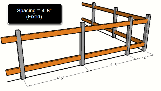
When 'Infill' components are set to 'Fixed' spacing (Max turned off) the spacing between infill components will be fixed to the value entered for spacing (where possible).
Component - Spacing (Horizontal)
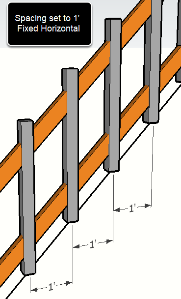
When 'Infill' components are set to 'Horizontal' spacing, the spacing will be measured horizontally. If this setting is turned off, then the spacing will be measured along the path of the Assembly.
Component - Layout
When max spacing is disabled, the components are distributed with the exact specified spacing where possible.
The various layout options have the following effects when max is disabled (fixed spacing)
Auto - From Middle or From Middle Gap will be used to distribute the components in a visually pleasing way. The number of components will be minimized.
From Start - The distance from the start component to the first infill component will be equal to the given spacing. The leftover spacing will be taken up between the last infill component and the last component.
From Middle - A component will be placed at the middle between the start and end components of the segment. Keep in mind that the setback values for the start, junction, and end components will affect the calculated middle location. Infill components will be placed at the given spacing starting from the middle component. The leftover spacing will be taken up equally at the start and end of the segment.
From Middle Gap - A gap will be placed at the middle between the start and end components of the segment. The gap distance will be equal to the given spacing value. Adjacent infill components will be placed at the specified spacing. Leftover spacing will be taken up equally at the start and end of the segment.
Only Middle - A single component will be placed at the middle between the start and end components of the segment. Keep in mind that the setback values for the start, junction, and end components will affect the calculated middle location.
When max spacing is enabled, the components are always distributed evenly using the maximum spacing as a guide. There is no leftover spacing in this case.
The various layout options have the following effects when max is enabled.
Auto - The components are with equal spacing between the start and end components along the segment. The number of components are minimized.
From Start - Same as 'Auto'.
From Middle - A component will be placed at the middle between the start and end components of the segment. Keep in mind that the setback values for the start, junction, and end components will affect the calculated middle location. Infill components will be distributed equally along the path segment.
From Middle Gap - A gap will be placed at the middle between the start and end components of the segment. Adjacent infill components will be distributed evenly.
Only Middle - A single component will be placed at the middle between the start and end components of the segment. Keep in mind that the setback values for the start, junction, and end components will affect the calculated middle location.
Component - Start, Junctions, and End Checkbox
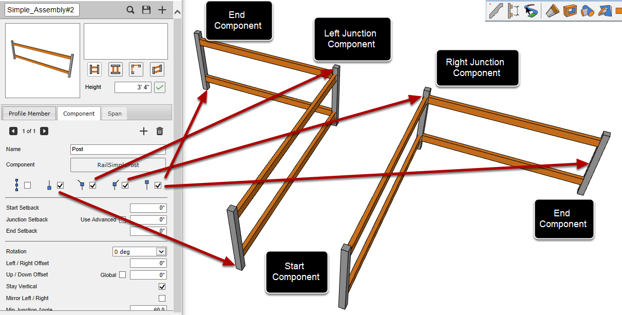
The Start, Junctions, and End checkboxes define whether to place components at the path start, path junctions (left or right), and at the path end.
Note that even if these checkboxes are disabled, the start, junction and end setback values will still be used to calculate the layout of any infill components.
Component - Start Setback, Junction Setback, End Setback
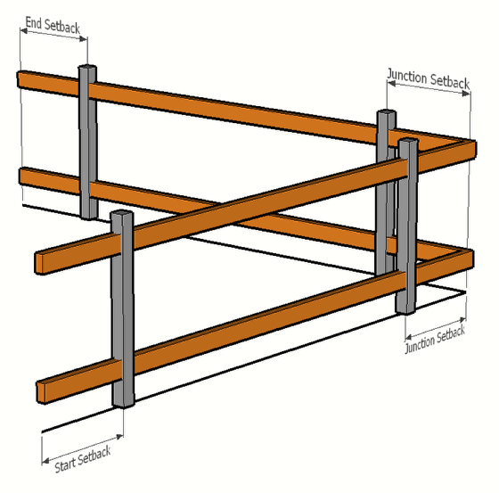
Start setback defines the distance from the path start to place the component. Use a negative value to position the start component before the start of the assembly path.
Junction setback defines the distance from the path junctions to place the component. If this value is not zero, a junction component will be placed on each side of the junction.
Advanced Junction setbacks can be enabled to give you more control on the setback values on either side of left or right junctions.
End setback defines the distance from the path end to place the component. Use a negative value to position the end component beyond the end of the assembly path.
Advanced Junction Setbacks

Component parts may use advanced junction setbacks. This allows greater control of the position of Components before and after junctions.
Component - Rotation
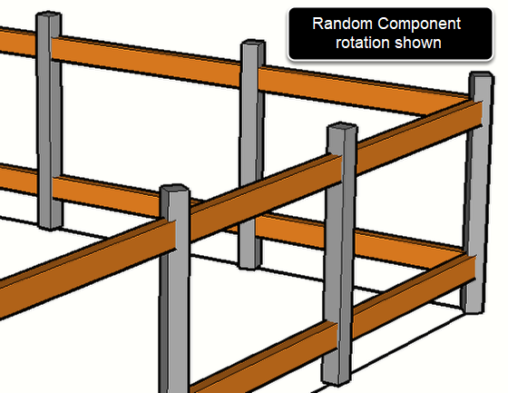
The Rotation setting defines the rotation of the component about it's Blue (up) axis. The options for rotation include:
- 0 deg (no rotation)
- 90 deg (1/4 turn)
- 180 deg (1/2 turn)
- 270 deg (3/4 turn)
- Average (no rotation except for at Junction locations. At junctions locations, the component rotation will be averaged between the previous path edge and the next path edge)
- Smooth (This setting can be useful for curved or helical paths)
- Random (each component will be rotated randomly)
Component - Scale Min / Max
New in v4! Input the minimum uniform scale of the component in the first box and the maximum uniform scale value in the second box. When the component is generated, it will be scaled randomly between the specified min and max values. To disable random scale, enter 1.0 in both boxes.
Component - Left / Right Offset
The Left / Right offset setting of a component is equivalent to the Left / Right offset setting of a Profile Member. See the Profile Member Assembly attributes above for further details.
Component - Up / Down Offset
The Up / Down offset setting of a component is equivalent to the Up / Down offset setting of a Profile Member. See the Profile Member Assembly attributes above for further details.
Component - Stay Vertical
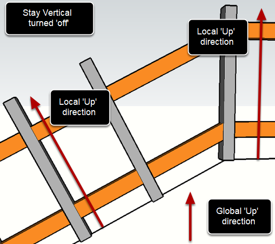
If the Component is set to 'Stay Vertical' then the Component's Blue axis will always point Up (along the blue axis), regardless of the path direction. If this setting is turned 'off', then the Blue axis will align with the local Up direction which is perpendicular to the direction of the Assembly path.
Component - Mirror Left / Right
If this setting is enabled, the Component will be mirrored about the Up direction of the Assembly path.
Component - Minimum Junction Angle
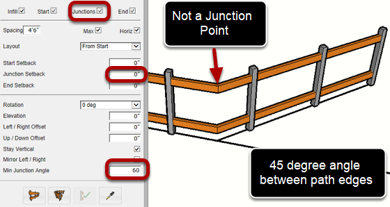
Minimum Junction Angle sets the angle between edges that is required to form a junction point. If the angle between path edges is greater than the minimum angle, the vertex will be treated as a junction point.
A junction point is a discontinuity in the layout and spacing of an infill component. Junction points divide an assembly path into segments.
Components can be located directly over junction points if the junction setback distance is set to zero.
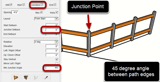
By decreasing the minimum junction angle to 45 degrees, a junction point will be created every time the assembly path changes direction by an angle of 45 degrees or more.
Tip: If you don't want your assembly path to ever create junction points for a component part, set the minimum junction angle to 180. This means that the assembly would need to make a 180 degree corner in order to create a junction point (which is not possible because Profile Builder does not allow 180 degree corners)
Comments
0 comments
Please sign in to leave a comment.